Thursday, June 30, 2011

COMMON MODELING TECHNIQUES

We have come to the part which you have to model your objects starting from lines and curves. The following techniques require you to draw the shapes of the object you want to model and apply the specific modifier.

LATHE SURFACE

In using the Lathe modifier, you must remember that you only have to draw the one side of a rounded object. Then, apply Lathe.

Usually, when I explain Lathe surfacing to my students I use the chalice as an example. It’s easy to draw and has very nice curves for a 3D model. So let me show you how to model a chalice using Lathe.

We’ll get the line from the Shapes button on the Create tab. It’s just beside the Geometry.


Figure 2-2. Shapes command panel.

In the Creation Method, the Initial Type is Corner and the Drag Type is Smooth. We want to be able to create the curves of the chalice by dragging and the pointed areas just by clicking.


Figure 2-3. The Creation Method.

With the combination of clicking and dragging, I start to draw the one side only of a chalice. You’ll need regular practice for you to understand how the curves and the pointed parts of the chalice are drawn. I only manage to understand this concept after I started teaching 3D Max to my first class in animation.


Figure 2-4. The Chalice as drawn on its one side only.

Then, I’m going to apply the Lathe modifier found in the Modify tab, Modifier List. Check it out.


Figure 2-5. Lathe modifier.

If you look at the object now it doesn’t quite look like a chalice. That’s because we still need to configure something in the Parameters section. With the object still highlighted, on the Parameters section on the right, click on the ‘Min’ button under the ‘Align’ group. There it is! Our chalice made by just a drawing of its one side.


Figure 2-6. Compete model of a chalice using Lathe.

Try This!

1. Now why don’t you start practicing by drawing some of the chess pieces such as the pawn, bishop, rook, and the queen! Just draw the one side and apply Lathe.

Note: Don’t forget to click the Min button on the Parameters or your object will not appear as what you want it to be.


Tuesday, June 28, 2011

Part 2 - Modeling

This part of the blog deals with modeling your 3D objects, from using standard geometric primitives to the more complex organic modeling. Modeling your 3D objects is usually the first step in creating 3D animations. In addition, this stage in animation is the hardest and longest compared to the rest of the steps in the animation process. Let’s start with the basics of modeling which are the geometric primitives.

A. Geometric Primitives

Primitives are the basic shapes in 3D animation. They are very familiar to us because most of these primitives we have learned from kindergarten to geometry in high school. It includes the simple circle and the more complex Torus. You can actually model a complex object from any of the primitives especially the box. I’ll introduce to you how to model simple objects using the standard geometric primitives found in 3DS Max.

BOX

The first primitive you can see on the command panel. In the figure below you can see a box on the Perspective. Focus your attention on the lower right portion of the command panel that says ‘Parameters’. Observe the different parameters you can use to modify your box object.


Figure 2-1. The Box primitive.

Try This!

1. Place a box on the front viewport by simply clicking on the ‘Box’ button on the command panel and drag it on the viewport.

2. At the lower portion of the command panel, go to ‘Parameters’ and place the mouse pointer on the ‘up-down’ buttons just beside the text box labeled ‘Length’.


3. Just drag it upwards or downwards until you reach the desired length of the box. Do the same for the width and height of the object. You can also type-in the values for the length, width, and height of the box if you want a more accurate measurement.

Try doing the same box as you can see below.


4. That’s how you model your box just by changing the values in the parameters section.

SPHERE

Just try and explore the rest of the primitives. For example here’s what you can change from the parameters section of a sphere.


Try This!

1. Change the number of segments from 32 to 5 and check out how your sphere will look like.

CYLINDER


Try This!

1. Check on box labeled ‘Slice On’ and move the arrow down beside ‘Slice From’ and you’ll see your new cylinder.

TORUS


CONE


PLANE


There are many primitives in Max that I will not cover in this book. I suggest you take a look at them and try them to see how you can use them in your models. In the activity below, we’ll make a simple 3D model of a table.

Try This!

1. Place a box in the Perspective viewport and follow the Parameters as shown in the figure below.


2. Now, place another box on the Top viewport somewhere at the lower left side of the first box. Use the following parameters. This will be the leg of the table.


3. With the box (leg) still selected, press the ‘Shift’ key and drag the box to the right, then release the Shift key. The ‘Clone Options’ dialog box will appear. Just leave the default settings as it is. Notice that we are going to copy only 1 box.


4. Do the same for the last 2 remaining legs of the table.


5. Our table is complete. All we have to do is to rotate all the objects together so that the model will look upright on its 4 legs. Select all the objects in the Front viewport and rotate the table upwards using the Rotate button.


6. There it is! Your 3D model of a table using boxes. Go and experiment on the different Geometric Primitives and try to model real world objects such as furniture and appliances.

LOWER INTERFACE BAR CONTROLS

In this part of Max’s user interface we focus our attention to the lower portion of the application. Most of the buttons found in this area are used in the animation of your models. The Viewport Navigation buttons which are located at the lower right of the Max interface will be used more often. These buttons will help you move around the viewports as you work with your models. In addition, let me show you the different parts of the lower portion of Max.

TIME SLIDER AND TRACK BAR

You use the Time Slider to move around the Track Bar. The Track Bar shows you the number of frames currently used in your animation. By default, the frame count is 100 and it approximately results to a 3 second animation. Eventually, you can configure the number of frames and I’ll show you where to do that after I’ll discuss the Status Bar and Key


Figure 1-17. The Lower Interface Bar with the Time Slider and Track Bar.

STATUS BAR

The Status bar indicates the position of your 3D objects on the active viewport. It also contains a description of what will be your next step.


Figure 1-18. The Status Bar.

KEY CONTROLS

These controls allow you to set the key frames when you start animating your objects. You will start using these buttons at the last part of this book.


Figure 1-19. Key Controls with the Auto and Set Keys.

TIME CONTROLS

The Time Controls have similar buttons to that of a media player. It has play, pause, move forward, and next buttons. But as I have mentioned, you can change the duration of your animation using the Time Configuration button.

Try This!

1. Click on the Time Configuration button at the lower right end part of the Time Controls.


2. In the Time Configuration dialog box, under the Animation section, change the Length of the animation from 100 to 200 frames. Then, click the OK button.


3. Now, your new Track Bar shows a total of 200 frames.


VIEWPORT NAVIGATION CONTROLS

There are buttons which can help you move around the viewports and these are the Viewport Navigation Controls. I’ll demonstrate some of the most useful of these buttons below.


Figure 1-20. The Viewport Navigation Controls.

Try This!

1. Place a Teapot in the Front viewport. Click on the Zoom button and drag it on any viewport. That’s how it works!

2. This time click on the Pan View button. Place the hand pointer on any viewport and drag it. It allows you to pan around the viewport.

3. Click on the Arc Rotate button and click the Perspective viewport. Notice that a yellow circle appears. You can click on any of the four small boxes and drag on it so that you can view the object in perspective view without actually rotating the object. Or you can simply drag the Perspective viewport to freely rotate the object.

4. Click on the Front viewport then click the Maximize Viewport Toggle button. Notice that the Front viewport in maximized. If you want to return to the original four viewports, just click on the Maximize Viewport Toggle button again.

Moreover, the Zoom Extents All button allows you to zoom all objects in all the viewports at the same time. Try it!

So that’s it! The Max user interface. As a review, I have prepared labels for the different parts of the interface below. So don’t forget!


Figure 1-21. 3DS Max User Interface.

In the next part of this blog, I will teach how to make your first 3D models!

Monday, June 27, 2011

The Command Panel

Let me show you the Command Panel. It has several tabs. But we’ll just use the Create, Modify, Hierarchy, and Display tabs in the entirety of this book. You can also access the different commands in the Command panel on the Main Menu bar.

CREATE TAB

In this tab you can find most of the options you need in creating your 3D models. It contains the Geometry, Shapes, Lights, Cameras, Helpers, Systems, and Space Warps. This is where you got the Teapot in the earlier section.


Figure 1-13. The Create tab.
MODIFY TAB

As what the name says, it lists all of the modifiers available for you to model your primitive shapes.


Figure 1-14. Modify list.

HIERARCHY TAB

Here, you will be able to change the pivot position of your rigged objects for moving, rotating, and scaling.


Figure 1-15. The Hierarchy Tab.

DISPLAY TAB

Under the Display Tab you can Hide objects when you don’t want to see them on your active viewport.


Figure 1-16. The Display tab.

Saturday, June 25, 2011

VIEWPORTS AND VIEWPORT OPTIONS (INCLUDING GIZMOS)

Viewports allow you to see your 3D objects in different view angles. There are four viewports in Max. By default, the Front, Top, Left, and the Perspective viewports are activated when you start the application. However, you can always change the views as I explain them to you in this section.


Figure 1-9. Default viewports when you start Max.

You can change the views by right-clicking on the viewport label. Then, choose ‘Views’. On the submenu, select the views you want.


Figure 1-10. Changing the views on the active viewport.

Also, you can change the way you view your objects in the pop-up menu. Choose ‘Smooth + Highlights’ if you want to see the actual 3D model. By default, Wireframe is selected.


Figure 1-11. Smooth + Highlights is selected.

Of course, there are the gizmos. These arrows are quite handy when you work with your 3D models.


Figure 1-12. The Gizmos.

Friday, June 24, 2011

The Main Toolbar


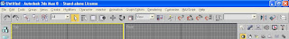
Figure 1-2 The Main Toolbar

The Main Toolbar is located just below the Main Menu. It has several buttons which I will introduce to you in this section.

UNDO AND REDO BUTTONS


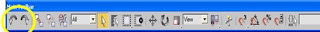
Figure 1-3. The Undo and Redo buttons (encircled).

These buttons are used every time you want to make changes to your work. But there’s a catch! You can only make until 20 undos. I have checked it out and it really does count only up to 20. Unlike MS Word, which you can list down all the changes you made to your document, you have to be sure of the changes you make to your MAX files.

SELECT AND LINK AND BIND TO SPACE WARP


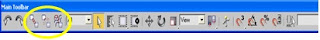
Figure 1-4. The Select and Link and Bind To Space Warp buttons.

If you want to link two or more objects, then you can use the SELECT AND LINK button. It works pretty much like on how you group objects in a document file. You can also link a 3D object to a space warp such as Bones. I’ll teach you how to use these buttons when we reach Part V which is Rigging and Animation.

By the way, you can place the mouse pointer on top of every button to see the label of the button you’re trying to use.

SELECT AND MOVE, ROTATE AND UNIFORM SCALE


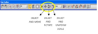
Figure 1-5. Select and Move, Rotate and Uniform Scale buttons.

We’ll be using these buttons more often than the other buttons found on the Main toolbar. Let me just go over and discuss briefly what these buttons do.

SELECT AND MOVE – When you want to select or move your objects in the space, you use the Select and Move button. Just a note, use this button if you want to change the position of the object/s you are working with in the virtual space. You will encounter another button which functions similarly with Select and Move but does not affect the position of the object you’re working.

SELECT AND ROTATE – Use this button when you want to rotate the object relatively in its position. Again, there’s another that works just the same as Select and Rotate. I’ll introduce these buttons later.

SELECT AND UNIFORM SCALE – Curiously, you can also change the length, width or both at the same time using the Select and Uniform Scale button. Don’t worry, you’ll be working with these three buttons shortly.

MIRROR AND ALIGN


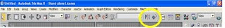
Figure 1-6. The Mirror and Align buttons.

Copying 3D objects in Max is also possible. There are two ways. One is to use the Mirror button and the other one is by pressing the SHIFT key and simply move the object. You can also align objects with the Align button.

MATERIAL EDITOR


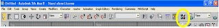
Figure 1-7. Material Editor button.

Placing colors or textures to your 3D objects will be done using the Material Editor. At first, your 3D objects will look barely in one color, just like the famous ghost cartoon Slimer. But when you start working with the Material Editor things can be really fun!

QUICK RENDER


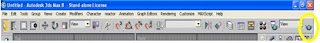
Figure 1-8. The Quick Render button.

I guess you have heard the term render before. As what the word says, the Quick Render button allows you to render your work without having to configure anything. You will learn more about rendering at the last part of this book. For now, why don’t you try out the activity I prepared for you?

Try This!

In this activity, I will orient you with the common buttons that you will be using more frequently than the other buttons found in Max.

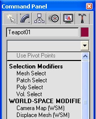
1. You may save your work as ‘Teapot-test.max’.
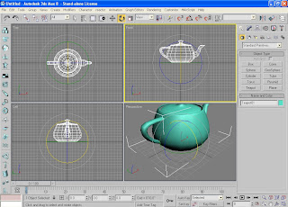
2. Locate the button ‘Teapot’ at the right side of Max. Then click on it.


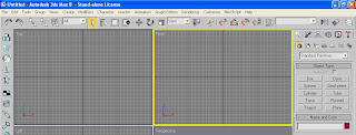
3. Place the Teapot on the ‘Front’ viewport. Just drag the object at the center of the viewport.


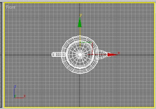
4. This time click on the Select and Move button on the Main toolbar. Notice that you will see two arrows in the Front viewport. The green arrow represents the Y axis while the red arrow represents the X axis. These arrows are called gizmos.

Now, I want you to move the teapot to the center of the Front viewport by placing your mouse pointer on the head of the green arrow. Just drag it upwards and downwards. Do the same for the red arrow, but this time drag it sideways.


5. There’s another way of doing that. Notice the two lines forming at the corner of the two arrows? Yes, place the mouse pointer on either of the lines, the green, the red, you choose. When the corner is highlighted, you can drag it anytime.


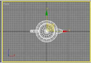
6. That’s about moving the object. Let’s turn the Teapot upwards so that it does not look like someone has just spilled tea on the floor. Click on the Select and Rotate on the Main toolbar this time.

7. Place the mouse pointer on the red line. Then, slowly drag it upwards.


8. Adjust its position move the Teapot exactly at the center of the Front viewport.

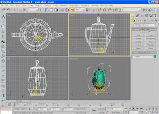
9. We’ll stretch our Teapot to make it look cartoony. Click on the Select and Uniform Scale button on the Main toolbar.

10. Place the mouse pointer on the green line (vertical). Then, drag it upwards. Stretch it!


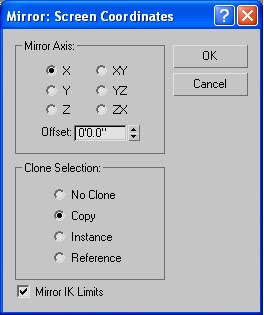
11. Let’s make a copy of our tall Teapot. Make sure the Teapot is still activated. You can say this if the object is highlighted in the viewports (line color is white). Click on the Mirror button on the Main Toolbar.

12. The ‘Mirror: Screen Coordinates’ dialog box will appear. Under the ‘Clone Section’, tick on copy. You may now click on the ‘OK’ button.


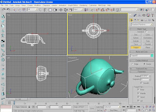
13. Using the Select and Move button, place the new Teapot beside the first one. Just like the figure below.


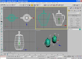
14. After this, you can take a quick look of your work by clicking on the ‘Quick Render’ button found still on the Main toolbar. Max will render the viewport that is active (highlighted in yellow line).

Well, I hope you liked what you’ve learned so far. I’ll continue introducing you to the other parts of Max interface.