
I will place an Arc in the Front viewport. This will be the path of the object. Then, a circle will do for the shape of my 3D model.

Figure 2-9. Arc path, and Circle shape.
This time, the Loft command is found in the Create tab instead in the Modify tab. In the Geometry panel choose ‘Compound Objects’ in the drop-down menu. You can find the Loft button at the bottom. Make sure you select either the Arc or the Circle to enable Loft.
 Figure 2-10. The Loft command button.
In my case, the Arc is selected. I will click on the ‘Get Shape’ button located at the ‘Creation Method’ group. Then, click on the Circle which is the shape of the loft object.

Figure 2-11. The Lofted object.
Notice how simple it is to do lofting. You can loft simple to complex objects. Why don’t you try the activity I prepared for you below? Good luck!

Figure 2-12. Perspective view of the lofted object.
Try This!
1. We’ll use the click and drag technique in drawing the path of the object. We’ll create a G clef object.
Click on the Line button and make sure the Initial Type is Corner and the Drag Type is Smooth. In this way we can apply the click and drag technique easily.

2. Maximize the Front viewport so that we can focus our attention to drawing the object. Place the mouse pointer at the center of the viewport then click (single press) on it and move the pointer to the upper right portion. Like this.

3. This time click the left mouse button and drag the pointer to the lower right side. Just follow the image below.

4. Then, as just what you did click and drag the mouse pointer according the to the path of the object we want to loft. Follow the points below where you need to click and drag.
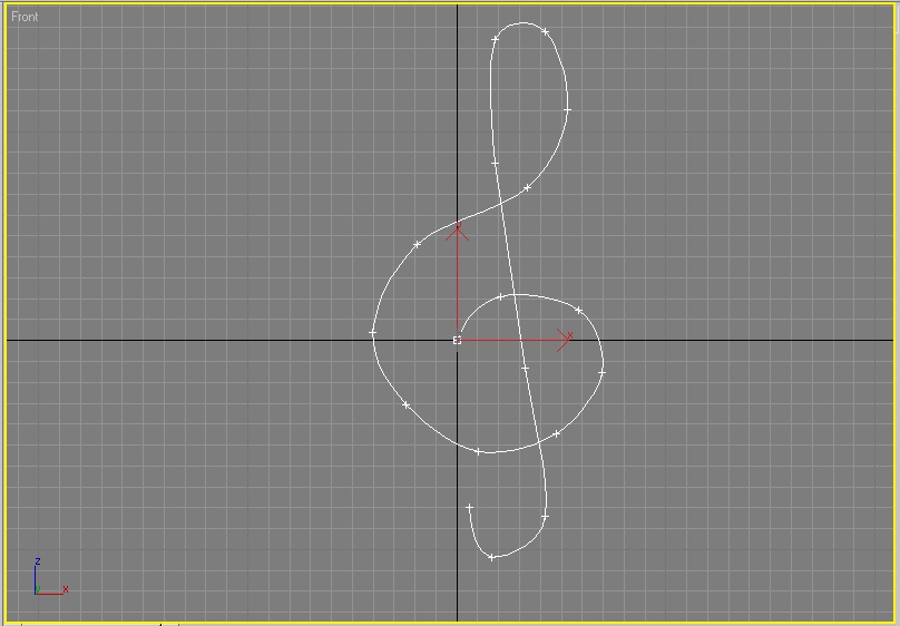
5. When you reach the last point, don’t click anymore instead you press the right mouse button to end the drawing.
6. For the shape of the object, we’ll choose the ellipse.

7. We are now ready to loft our object. Go to the Geometry panel, select the Compound Objects in the drop-down list. Click on the Loft button. Make sure that the path (which is the drawing) is selected.

8. Click on the Get Shape button and place the mouse pointer on the ellipse and click on it.

9. There it is! Our 3D version of the G clef.


